

Why SEBS Modification Requires Twin Screw Precompounding
A complete analysis of viscosity ratio, capillary number, SME, and foam cell stability
A technical guide to EVA/POE/SEBS foam formulations, explaining how POE reduces hardness and improves rebound, how SEBS reinforces interfaces and cell walls, and how twin-screw dispersion affects cell uniformity, tear resistance, and dimensional stability.
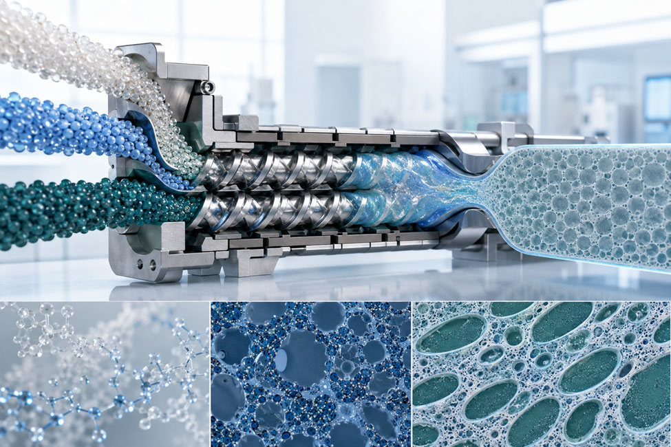
EVA, POE, and SEBS are pre-compounded in a twin-screw extruder to establish a controlled multiphase dispersion structure.
1 The Role of SEBS in Creating Stress Bearing Microdomains
SEBS is a styrene-ethylene/butylene-styrene triblock copolymer. At room temperature, its polystyrene (PS) end blocks aggregate into hard microdomains because of their higher glass transition temperature. The hydrogenated ethylene/butylene (EB) midblock retains a low Tg and rubber-like elasticity. The PS microdomains act as reversible physical crosslinks, giving SEBS elasticity, creep resistance, and the ability to withstand tearing loads even without chemical vulcanization.
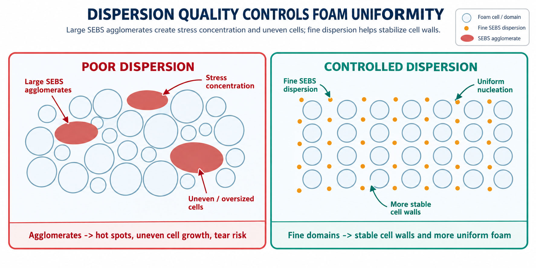
When SEBS is added to an EVA/POE foam system, the aim is to create a finely dispersed phase with a uniform distribution and good interfacial adhesion, rather than to mix all molecules into a single phase. The EB midblock has greater affinity for polyolefin chain segments, while the hard PS microdomains can improve melt elasticity and resistance to crack propagation. However, if SEBS remains in agglomerates hundreds of micrometers or even millimeters in size, the benefits of these hard microdomains can instead become unmelted particles, stress concentrations, and foam cell defects.
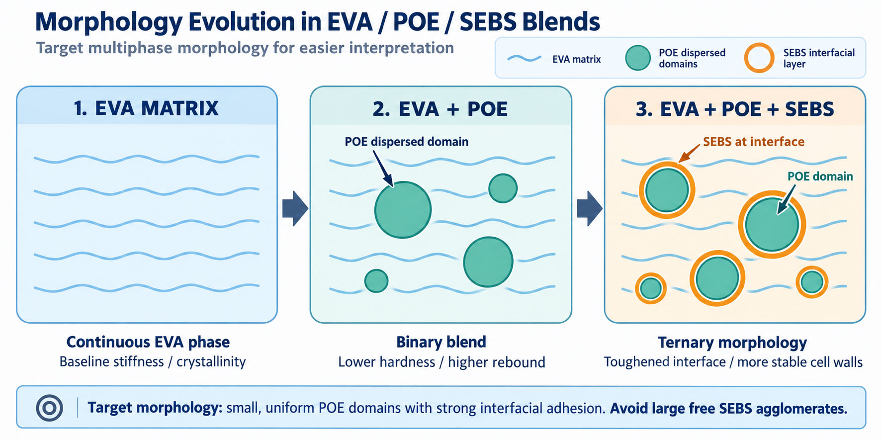
Four Potential Benefits of SEBS
Improved tear and fatigue resistance: the rubbery midblock absorbs energy, while hard PS microdomains hinder crack propagation.
Greater melt elasticity: helps cell walls withstand biaxial stretching, reducing cell coalescence and collapse.
Improved cushioning and feel: enables adjustment of the DMA loss peak and recovery rate.
Less reliance on a single low melting point POE: may help balance softness, toughness, and dimensional stability after downstream processing.
2 Why SEBS Is More Difficult to Disperse than Conventional POE
1 High Molecular Weight and Melt Viscosity
Most SEBS toughening grades rely on higher molecular weight to maintain network strength. Their viscosity at processing temperatures may therefore be substantially higher than that of EVA or low viscosity POE. When the viscosity ratio between the dispersed phase and the matrix falls outside a suitable range, external shear stress does not readily penetrate SEBS agglomerates. Their surfaces may stretch while their cores remain intact.
2 Hard PS Microdomains Resist Agglomerate Breakup
During feeding and initial melting, the glassy microdomains of the PS end blocks give SEBS particles relatively high cohesive strength. Agglomerates gradually soften and break apart only after sufficient heating, shear, and repeated interface renewal. Simply extending the processing time may be ineffective because thermo-oxidative degradation, yellowing, and MFR drift may occur first.
3 Oil Absorption Oil Content and Feeding History
Some SEBS grades are oil extended, or the formulation may require white mineral oil to reduce viscosity. The oil addition sequence determines whether oil first enters the SEBS phase, the EVA/POE phase, or the interface. Adding large amounts of oil too early may reduce stress transfer and make agglomerates harder to break up. Uneven oil distribution may also cause surface oil bleed, localized tackiness, and batch variation.
4 Interfacial Limitations between Polar EVA and Nonpolar SEBS
As the vinyl acetate (VA) content of EVA increases, the difference in solubility parameters between EVA and nonpolar SEBS/POE generally becomes more pronounced. Even when macroscopic mixing is possible, interfacial tension may cause dispersed phases to coalesce again in low shear regions. Compatibilization strategies using EVA-g-MAH, SEBS-g-MAH, or EAA may be evaluated where necessary, but compatibilizers cannot replace adequate softening and dispersion.
3 Dispersed Phase Breakup Capillary Number and Viscosity Ratio
The breakup of droplets or softened agglomerates in a flow field can be described by the capillary number: Ca = ηm · γ̇ · R / σ. Here, ηm is the matrix viscosity, γ̇ is the shear rate, R is the dispersed phase radius, and σ is the interfacial tension. The dispersed phase can stretch and break up only when the deformation stress generated by flow is sufficient to overcome interfacial tension.
A higher Ca is not always better. If SEBS has not softened sufficiently, it behaves as a solid agglomerate rather than an ideal droplet. Excessive local shear may also cause chain scission and thermal oxidation. The viscosity ratio, λ = ηd / ηm, also affects breakup efficiency. When the dispersed phase viscosity ηd is much higher than the matrix viscosity, elongational flow, kneading, and repeated folding are needed to reduce the phase size effectively.
| Parameter | When too low | When too high | Control approach |
|---|---|---|---|
| Matrix viscosity ηm | Insufficient stress transfer | Higher melt temperature and load | Establish a workable window through temperature and grade selection |
| Shear rate γ̇ | Difficult agglomerate breakup | Degradation, overheating, higher MFR | Balance kneading block angle and screw speed |
| Interfacial tension σ | Favors refinement but may cause excessive compatibilization | Coalescence and weak interfaces | Select compatible materials and compatibilizers |
| Viscosity ratio λ | Dispersed phase stretches readily but may coalesce | SEBS cores are difficult to break up | Adjust preheating, oil addition sequence, and mixing zones |
4 Twin Screw Extrusion Provides More than Stronger Shear
A co-rotating intermeshing twin-screw extruder uses modular conveying elements, kneading blocks, reverse elements, and distributive mixing elements to establish different functional zones along the barrel. Its core advantage is the simultaneous control of residence time distribution, interface renewal frequency, local shear, elongational flow, venting, and melt temperature in a continuous process.
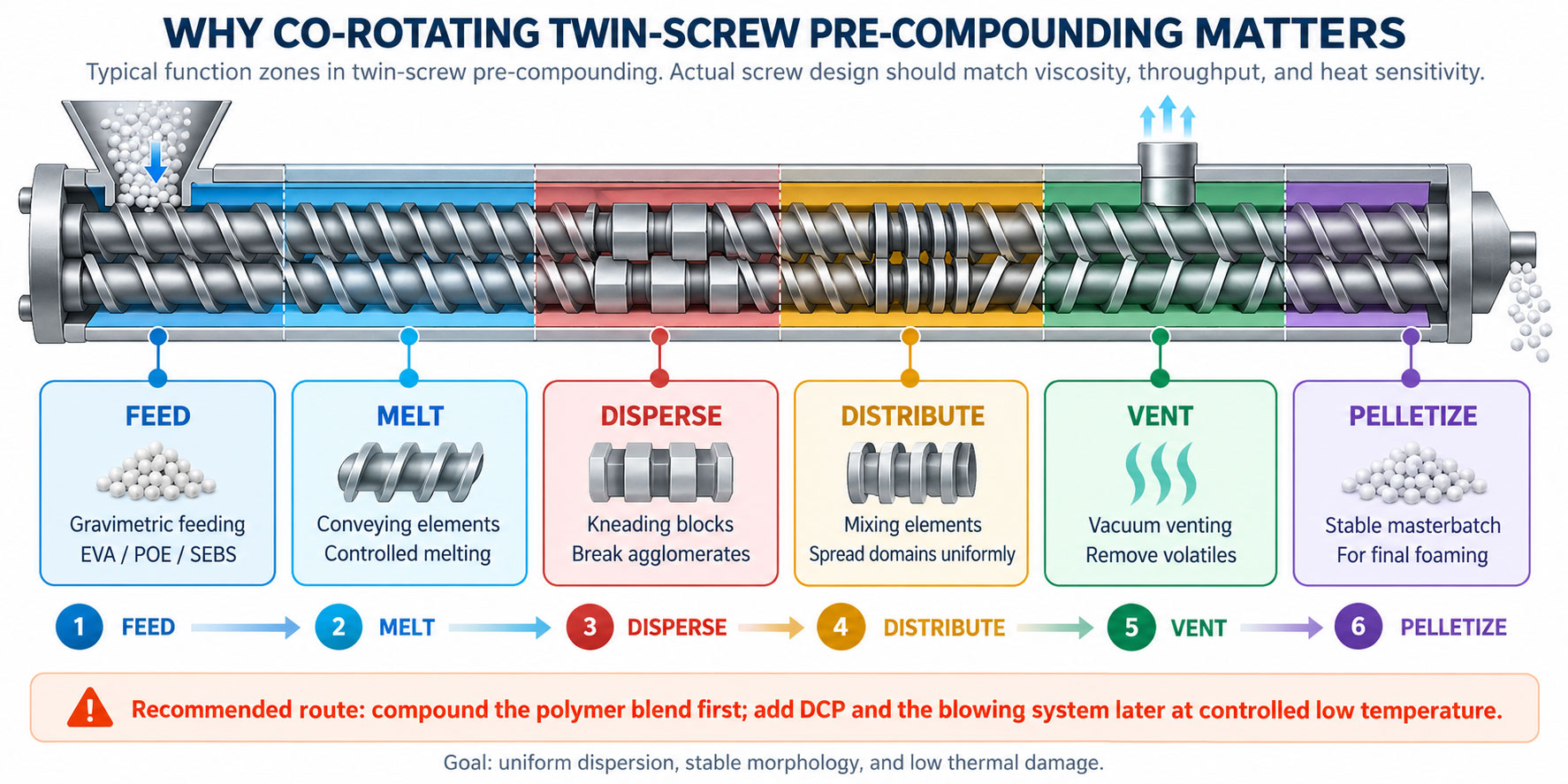
Distributive Mixing and Dispersive Mixing
| Mixing mechanism | Primary task | Effect on SEBS | Typical elements or conditions |
|---|---|---|---|
| Distributive mixing | Distribute components uniformly throughout the melt | Reduce concentration differences and batch segregation | Wide pitch conveying elements; toothed or flow splitting elements |
| Dispersive mixing | Overcome agglomerate cohesion and reduce phase size | Break up unsoftened SEBS and large phase domains | 30°/45°/60° kneading blocks; reverse elements |
| Elongation and interface renewal | Stretch and fold the melt to create new interfaces | Improve compatibilizer contact and interfacial adhesion | Intermeshing zones, mixing elements, and multiple kneading sections |
| Devolatilization and pressure stabilization | Remove moisture and volatiles; reduce feed pulsation | Reduce bubbles, silver streaks, and pellet voids | Vacuum ports, melt seals, and stable metering |
| Key concept: good distribution with poor dispersion leaves large SEBS particles throughout the melt. Good dispersion with poor distribution produces localized enrichment. Both are required. |
5 SME as a Process Indicator beyond Screw Speed
Specific mechanical energy (SME) approximates the mechanical energy input per unit mass of melt and is commonly calculated from motor power, torque, screw speed, and throughput. Increasing screw speed does not necessarily improve actual dispersion because throughput, fill level, and material temperature change at the same time. At the same rpm, SME may increase substantially if the feed rate decreases, viscosity rises, or more kneading elements are used.
During development, record torque, SME, actual melt temperature, throughput, vacuum level, and MFR drift together. If black specks or hard particles decrease while MFR rises significantly, the change may indicate chain scission or thermo-oxidative degradation rather than improved dispersion.
| Monitoring variable | What it indicates | Abnormal signal |
|---|---|---|
| Torque/load | Material viscosity, fill level, and element resistance | Large fluctuations: unstable feeding or softening |
| SME | Mechanical energy per unit mass | Too low: insufficient dispersion; too high: degradation risk |
| Melt temperature | Actual thermal history rather than barrel setpoints | Too high: yellowing, odor, and higher MFR |
| Vacuum level/volatiles | Removal of moisture, oil mist, and low molecular weight substances | Pellet voids, silver streaks, or odor |
| MFR change before and after processing | Chain scission, crosslinking, or composition changes | Marked increase: degradation; decrease: reaction or gels |
6 Preparing the Polymer Masterbatch before Adding DCP and the Blowing System
DCP and chemical blowing agents are both affected by cumulative time-temperature exposure. If they pass through high shear kneading zones for a prolonged period together with high viscosity SEBS, premature decomposition, loss of effective activity, or localized scorching may occur. This disrupts the timing of crosslinking and gas generation during subsequent compression molding, increasing cell size variation, expansion ratio drift, and safety risks.
1. Stage one feeding: feed EVA, POE, and SEBS using loss-in-weight feeders. Add oil or compatibilizer in stages where necessary.
2. Twin-screw pre-compounding: first complete softening, agglomerate breakup, distributive mixing, and vacuum venting.
3. Cooling and pelletizing: produce a polymer masterbatch with stable composition and phase morphology.
4. Stage two low temperature mixing: then add DCP, blowing agents, activators, and other heat-sensitive additives.
5. Conditioning and compression molding: standardize masterbatch moisture content, conditioning time, mold center temperature, mold opening, and cooling conditions.
7 Designing the Screw Configuration
| Functional zone | Design objective | Common error | Adjustment approach |
|---|---|---|---|
| Solids conveying | Stable filling; avoid bridging and segregation | SEBS particle shape variation causes feed pulsation | Loss-in-weight feeding, preblending, and feed zone cooling |
| Melting | Establish a continuous EVA/POE melt first | High shear too early scorches SEBS surfaces | Conveying elements combined with gentle kneading |
| Dispersion | Break up high viscosity SEBS agglomerates | Weak kneading or insufficient residence time | Increase intermediate angle kneading and local fill level |
| Distribution | Repeated flow splitting, folding, and interface renewal | Dispersion without distribution causes localized enrichment | Add distributive mixing elements |
| Venting | Remove moisture, volatiles, and oil mist | Insufficient melt seal causes material carryover at the vent | Establish a pressure seal before the vent |
| Metering and pelletizing | Stable pressure, pellet size, and batch quality | Excessive temperature or residence time near the discharge | Reduce backpressure and improve cooling |
There is no universally applicable arrangement of screw elements. SEBS molecular weight, oil extension level, addition rate, EVA VA content, POE viscosity, and throughput all affect the optimum configuration. Use morphology, SME, melt temperature, and final foaming results together to guide the design rather than simply copying another screw layout.
8 When Twin Screw Precompounding Is Necessary
Scientifically, twin-screw extrusion is not the only way to modify a formulation with SEBS. Acceptable dispersion may also be achieved when the SEBS content is low, the grade softens readily, the matrix viscosity is well matched, and an internal mixer provides sufficient energy and good batch control. However, with high molecular weight SEBS, high addition levels, multiple components, compatibilizers, or demanding production consistency requirements, a co-rotating twin-screw extruder generally makes it easier to establish a repeatable, quantifiable process window.
| Condition | Internal mixing or single screw may be considered | Twin-screw pre-compounding preferred |
|---|---|---|
| SEBS content | Low addition level; readily softened grade | Medium to high addition level or high molecular weight grade |
| Quality requirements | Broader tolerances for appearance and properties | High batch consistency for insoles, midsoles, and protective pads |
| Formulation complexity | Few components; matched viscosity | Multiple components: EVA/POE/SEBS/oil/compatibilizer |
| Validation results | No hard particles; stable phase size and properties | Existing gel particles, coarse cells, tear or shrinkage issues |
9 Verifying Improved Dispersion
| Assessment level | Suggested methods | Information obtained |
|---|---|---|
| Rapid process checks | Torque, SME, melt temperature, screen pressure differential | Batch energy, thermal history, and trends in unmelted particles |
| Masterbatch appearance | Optical microscopy, stained sections, surface scanning | Black specks, hard particles, agglomeration, and particle size distribution |
| Advanced morphology | SEM/AFM; selective etching | Dispersed phase size, interfaces, and phase inversion |
| Thermal and dynamic mechanical analysis | DSC; DMA frequency and temperature sweeps | Crystallization, Tg, PS microdomains, and degree of compatibility |
| Rheology | Frequency sweeps, Cole-Cole analysis, melt strength | Network formation, low frequency elasticity, and cell wall potential |
| Final foam | Density, cells, tear resistance, rebound, compression set | Whether morphology delivers benefits in the finished product |
| Three levels of success: first, assess the masterbatch for unmelted particles, stable phase size, and controlled MFR drift; second, check foam density and cell consistency; third, confirm that tear resistance, rebound, compression set, and dimensions after bonding improve relative to the original formulation. |
10 Troubleshooting on the Production Floor
| Issue | Possible causes | Priority actions |
|---|---|---|
| Hard particles in masterbatch | SEBS not sufficiently softened, short residence time, or unstable gravimetric feeding | Increase preheating/residence time; adjust kneading zones and loss-in-weight feeding |
| Significant MFR increase | Shear or thermo-oxidative degradation | Reduce SME and melt temperature; improve venting and antioxidant protection |
| Pellet voids | Moisture or volatiles not removed | Improve drying, vacuum venting, and melt seals |
| Large variation in foam cell size | Uneven phase size or DCP/blowing agent dispersion | Pre-compound and pelletize first; add the reactive system in stage two |
| Reduced tear resistance | SEBS agglomeration, weak interfaces, or excessive oil extension | Check morphology, viscosity ratio, oil addition sequence, and compatibilizer |
| Tacky surface or oil bleed | Oil level exceeds the SEBS oil absorption balance | Verify grade oil content, total oil level, and conditioning conditions |
Conclusion Turning Material Potential into a Morphology Suitable for Production
Through its hard PS microdomains and soft EB segments, SEBS can improve melt elasticity, tear resistance, fatigue resistance, and cell wall strength in EVA/POE foams. These benefits appear only when SEBS is sufficiently softened, phase domains are refined, and interfaces are stable. Undispersed SEBS acts as gel particles, weak interfaces, and foam cell defects rather than as a toughening phase.
The value of co-rotating twin-screw pre-compounding extends beyond increasing shear. It turns melting sequence, viscosity matching, dispersive and distributive mixing, venting, SME, and thermal history into recordable and repeatable production parameters. Adding DCP and chemical blowing agents during a second low temperature stage helps balance dispersion, the reaction window, and safety.